Monthly Archives: April 2012

Radio parts for my near-space balloon project

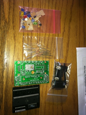
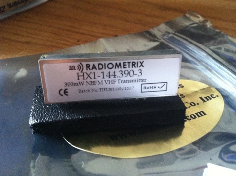
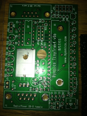
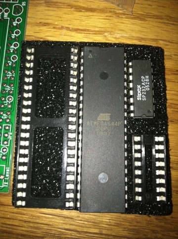
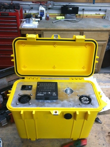
I am assembling my own electronics for an APRS based weather balloon project. I’ll be launching a balloon with some friends that transmits various weather data and location via APRS ham radio, and also logs high resolution data via a basic stamp computer.

20120426-173505.jpg

20120426-173456.jpg

20120426-173511.jpg

20120426-173517.jpg

Posted in N0BCB Tagged |

Adjustable mounts I built

I built these for a client to mount environmental telescope enclosures on rooftops. They are welded from 1/4″ wall Aluminum tubing, and have azimuth and height adjustments.

20120418-080736.jpg

20120418-080743.jpg

Posted in B's Blog Tagged |

Kenwood TH-D72A Frequency Unlock

Today I decided to attempt the unlock procedure I found on the web for the TH-D72A. There are a few different ideas out there that differ from each other. I looked around a lot, and the one I tried worked! I thought I’d add some additional photos here to make it easier for people to do this on their own. All the other sites I found were forums, and those sometimes drive me crazy to read through. Before you get started, use MCP-4 Kenwood programming software to back up all your radio settings!
The first step is to remove the antenna and the 2 knobs on the top of the radio. The knobs simply pull straight off. After you are done that, remove the battery, and then remove the 2 small black screws that are near the bottom of the radio, under the battery.
Photo & Video Sharing by SmugMug
Remove the rubber cover that protects the ports on the side of the radio (USB, speaker, etc). To do this, you will notice a small rubber flap under the battery, near the middle of where all the rubber flaps are. Use a small regular screwdriver to pry the rubber up and over the metal stud, then just pull the rubber flap assembly off. Once this had been done, you can carefully lift the body of the radio up and remove it from the housing.
Photo & Video Sharing by SmugMug
If the rubber key membrane did not stay in the housing, remove it from the radio body now so that you can access the circuit board.
There are 2 diodes that need to be removed, Diode #729 and Diode #730. Diode #729 is located near the bottom of the circuit board. Use a small tip soldering iron and a pair of tweezers. I used a very small screwdriver to put pressure on one side of the diode, the pushed slightly as I heated the solder joint on that side. Once it moved a little, I held it with tweezers while I heated the other side. I taped the diode to a post-it note, labeled it, and saved it in the radio box.
Here is a photo of diode #729.
Photo & Video Sharing by SmugMug
To remove the other diode, you’ll need to remove the screw that holds the speaker assembly in place. Once the screw is removed, hinge the speaker over the cable and remove the diode labeled 1, saving it with the other.
Diode 1 before removal:
Photo & Video Sharing by SmugMug
Diode 1 after removal:
Photo & Video Sharing by SmugMug
The radio is now ready for re-assembly, in the reverse order. One thing I had difficulty with was the rubber key overlay. I found that in order to reinstall the radio body into the housing case, you must put the rubber key overlay onto the radio body first, not into the housing first.
Photo & Video Sharing by SmugMug
Do a factory reset: MENU > RADIO > AUXILIARY > RESET > FULL RESET
The radio now has expanded Tx ranges. I like this option so that I can communicate over FRS or GMRS bands with non-HAM operators.

Posted in B's Blog, N0BCB Tagged , , |

Erin Bibeau Photography — Fort Collins!

For all your Fort Collins, Colorado and surrounding area photography needs, including portrait, baby, family and wedding, contact Erin!

Erin Bibeau Photography
970.219.8703
P.O. Box 235
Fort Collins, CO 80526
www.erinbibeau.com

Posted in B's Blog Tagged |

Smoker!

A co-worker gave me an old Brinkman smoker today. I fired it up tonight for a top sirloin, chicken and veggies. Yum! I’ve never cooked such a delicious steak! I used whole foods real charcoal and soaked apple wood chips.

20120409-201758.jpg

Posted in B's Blog Tagged |

Spring Colorado sky

20120407-164517.jpg

Posted in B's Blog Tagged |

Building a temperature well

Finally finishing up a project I started a few months back. This is a peltier junction temperature well for calibrating meteorological sensors.

Peltier cooled temperature well

The Peltier junction is controlled via an Omega PID controller, and utilizes an h-bridge for switching polarity to the cooler. An RTD sensor provides temperature feedback to the PID. This allows the well to be heated or cooled for different testing levels. I turned the well out of Aluminum, with a 1.50″ ID, so that it will receive off-the-shelf aluminum inserts for different sensors. The inserts can be drilled out to match whatever unit you have under test. I’m also going to make one insert that allows for propylene glycol baths.
20120403-140214.jpg

This first unit was a bit of a science experiment. I will be building 2 more of these as “final” products for work, and for those I’ll lay out a circuit board to handle all the electrical connections, so that each component can be plug-able.
20120403-140232.jpg
This unit is capable of -10C to +50C under normal conditions. Right now it has a 3-stage Peltier thermoelectric junction. I’m going to add another 3-stage unit. -50C is my goal for adjusting the offset on temperature sensors. If anybody is interested in one of these, I can make you one!

Posted in B's Blog Tagged , |

Lathe project

Did a small job on Saturday repairing a farm implement for a coworker. I had to cut off the damaged threads, bore it out and tap it, then install an exhaust stud with loctite.

20120403-135920.jpg

20120403-135908.jpg

Posted in B's Blog Tagged |