Category Archives: N0BCB

HAM radio call sign, N0BCB, previously KD0PVZ.

Yaesu FT-817ND with Buddistick vertical

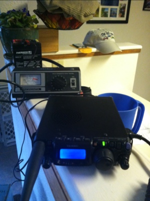
Made big headway today with my new setup. I had only made one contact so far and was getting frustrated. The SWR meter on my 817 showed nothing so I assumed everything was tuned correctly. I finally hooked up my old Micronta 21-525B gifted to me by K1LQH, and found my SWR on CW was 3:1! I shortened the whip about 12″ and immediately was copied 5-9 by a station in CT and another in MD!

20120811-205941.jpg

Tagged |

10 meter antenna part II

I used Nylon rod turned on my lathe to mount the mast to the ground plate. I may switch to fiberglass later, but cheap is my goal and I had the Nylon and PVC pipe for the vertical. I used 14 gauge Romex stripped out for the conductors. At the top of the PVC I’ll add a plastic compression fitting to seal the copper that extends just beyond the pipe.

20120729-190525.jpg

20120729-190535.jpg

20120729-190545.jpg

Tagged |

Homebrew 10 meter vertical

I’m working on a 10 meter vertical antenna for the roof of my house. It’s a quarter wave ground plane centered on 28.8 MHz, so it will be 97.5″ tall with 4 97.5″ radials. I used the formula Length of Dipole (feet) = 468 / Frequency (MHz). Since the radials comprise one half of the dipole and the vertical is the other half, you divide the length by 2.
I’m looking for some 1/4″ diameter fiberglass rod for the vertical. We get a lot of wind in Colorado so it needs to be tough. The base is a 1/4″ thick aluminum plate with a SO-239 bulkhead connector. I will weld on a round piece of stock on the top side, then turn it on my lathe as a receiver for the fiberglass rod. A length of 14 gauge stranded copper will live inside the fiberglass tube.
Here are some pictures of the base that I started on today:

20120729-145340.jpg

20120729-145351.jpg

Tagged |

Radio parts for my near-space balloon project

I am assembling my own electronics for an APRS based weather balloon project. I’ll be launching a balloon with some friends that transmits various weather data and location via APRS ham radio, and also logs high resolution data via a basic stamp computer.

20120426-173505.jpg

20120426-173456.jpg

20120426-173511.jpg

20120426-173517.jpg

Tagged |

Kenwood TH-D72A Frequency Unlock

Today I decided to attempt the unlock procedure I found on the web for the TH-D72A. There are a few different ideas out there that differ from each other. I looked around a lot, and the one I tried worked! I thought I’d add some additional photos here to make it easier for people to do this on their own. All the other sites I found were forums, and those sometimes drive me crazy to read through. Before you get started, use MCP-4 Kenwood programming software to back up all your radio settings!
The first step is to remove the antenna and the 2 knobs on the top of the radio. The knobs simply pull straight off. After you are done that, remove the battery, and then remove the 2 small black screws that are near the bottom of the radio, under the battery.
Photo & Video Sharing by SmugMug
Remove the rubber cover that protects the ports on the side of the radio (USB, speaker, etc). To do this, you will notice a small rubber flap under the battery, near the middle of where all the rubber flaps are. Use a small regular screwdriver to pry the rubber up and over the metal stud, then just pull the rubber flap assembly off. Once this had been done, you can carefully lift the body of the radio up and remove it from the housing.
Photo & Video Sharing by SmugMug
If the rubber key membrane did not stay in the housing, remove it from the radio body now so that you can access the circuit board.
There are 2 diodes that need to be removed, Diode #729 and Diode #730. Diode #729 is located near the bottom of the circuit board. Use a small tip soldering iron and a pair of tweezers. I used a very small screwdriver to put pressure on one side of the diode, the pushed slightly as I heated the solder joint on that side. Once it moved a little, I held it with tweezers while I heated the other side. I taped the diode to a post-it note, labeled it, and saved it in the radio box.
Here is a photo of diode #729.
Photo & Video Sharing by SmugMug
To remove the other diode, you’ll need to remove the screw that holds the speaker assembly in place. Once the screw is removed, hinge the speaker over the cable and remove the diode labeled 1, saving it with the other.
Diode 1 before removal:
Photo & Video Sharing by SmugMug
Diode 1 after removal:
Photo & Video Sharing by SmugMug
The radio is now ready for re-assembly, in the reverse order. One thing I had difficulty with was the rubber key overlay. I found that in order to reinstall the radio body into the housing case, you must put the rubber key overlay onto the radio body first, not into the housing first.
Photo & Video Sharing by SmugMug
Do a factory reset: MENU > RADIO > AUXILIARY > RESET > FULL RESET
The radio now has expanded Tx ranges. I like this option so that I can communicate over FRS or GMRS bands with non-HAM operators.

Also posted in B's Blog Tagged , , |

UV3D APRS working!

My problem turned out to be power related. Whenever the TT3 would transmit, the voltage would drop to around 4.7v and it would reset. I added a LM7805 with 4 AA batteries, and it is working reliably now. I also moved it from the breadboard to a circuit board so I can test it on the highway.
20120301-223516.jpg

20120301-223523.jpg

20120301-223528.jpg

Tagged |

Wouxun UV3D APRS

Finally was able to get my homemade APRS transmitter working tonight! I’m using a Byonics TinyTrak 3 SMT TNC with a Parallax GPS, hooked to my Wouxun HT. There seems to be something weird going on with the PTT circuit that I haven’t quite figured out yet. The TT3 doesn’t always seem able to pull down the 5V PTT singnal on the handheld. I’m thinking about adding an external transistor if I can’t get it to work reliably.

20120301-202102.jpg

Tagged |